Raspberry Pi Pinout
This tutorial will discuss checking the pinout of a Raspberry Pi using the python3-gpiozero package on Raspberry Pi OS.
Raspberry Pi Pinout
A Raspberry Pi has a lot of pins on it, like 40 pins on Raspberry Pi 3, but the Raspberry Pi board does not mention any port number or name, unlike an Arduino board which mentions pin names and numbers. We can check the pinout of a Raspberry Pi using the terminal of Raspberry Pi OS.
We have to type pinout in the terminal of a Raspberry Pi OS, which will show the pinout of the Raspberry Pi on which the Raspberry Pi OS is running. The python3-gpiozero package is already installed in the newer versions of the Raspberry Pi OS, and the pinout command will work on the terminal.
If the pinout command does not work, we have to install the python3-gpiozero package using the below commands on the terminal of Raspberry Pi OS.
sudo apt update
sudo apt upgrade
sudo apt install python3-gpiozero
We have to run each of the above commands on the terminal. The first two commands are used to update the installed packages of a Raspberry Pi OS, and the third command will install the package needed to run the pinout command.
While running the above commands, the terminal might ask for permission, and we must enter y to install the package. After installing the package, we can type pinout in the terminal, which will list the Raspberry Pi’s pins.
For example, let’s run the pinout command on a Raspberry Pi 1. See the code and output below.
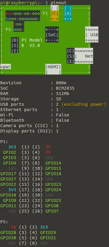
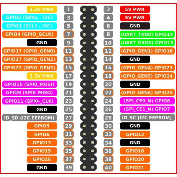
We can see in the above output that all the information about the Raspberry Pi is shown along with the 26 pins present in a Raspberry Pi 1 model. The newer models of a Raspberry Pi, like models 2, 3, and 4, have 40 pins shown below.
The above Raspberry Pi has four power pins, of which are 5-volt and 3.3-volt pins. There are 8 ground pins; the rest are GPIO pins, also known as general purpose input output pins.
The GPIO pins are digital and can be used as inputs or outputs. Some GPIO pins, like pin 21 in the above image, are used for SPI or serial peripheral interface which can be used to connect and control another device with Raspberry Pi, which can act as a master or slave.
Some GPIO pins, like pin 27 in the above image, are used for I2C or inter-integrate circuit communication which can be used to send and receive data from a EEPROM or electrically erasable programmable read-only memory. Some GPIO pins, like pin 8 in the above image, are used for UART or universal asynchronous receiver or transmitter, which can be used for serial communication between two devices.
Some GPIO pins, like pin 38 in the above image, are used for PCM or pulse code modulation, which can be used to represent analog data as digital samples, which means we can use these pins to receive analog data and convert it into digital data. Some GPIO pins, like pin 32 in the above image, are used for PWM or pulse width modulation, which can be used to control the speed of DC motors and brightness of LEDs.