Arduino Pull-Down Resistor
- Understanding Pull-Down Resistors
- Using Pull Down Resistor With a Switch in Arduino
- Implementing Pull-Down Resistors in Arduino
- External Pull-Down Resistor with Analog Pin in Arduino
- Internal Pull-Up Resistor With a Switch in Arduino
- Conclusion
When working with switches and digital inputs in Arduino, it’s crucial to manage the state of the input pin when the switch is not actively pressed. Pull-down resistors are commonly used in such scenarios to ensure a predictable and stable state.
This article explores different methods of implementing pull-down resistors with a switch in Arduino, providing example codes for each method along with detailed explanations. We will discuss how to use a pull-down resistor with a switch in Arduino.
Understanding Pull-Down Resistors
A pull-down resistor is a resistor connected between the input pin and ground (GND) in a circuit. Its purpose is to ensure that the input pin reads a known logic state (usually LOW) when the switch is open or not pressed.
When the switch is pressed, it connects the input pin to the voltage source (VCC), overriding the pull-down resistor and making the input HIGH.
Purpose of Pull-Down Resistors
Pull-down resistors are essential components in digital circuits, particularly when dealing with switches or push buttons. They ensure a stable and well-defined voltage level when the switch is open, preventing the input pin from floating and providing a clear signal to the microcontroller.
Floating State Issue
Without a pull-down resistor, when a switch is open, the input pin is left floating, leading to unpredictable and unstable readings. This floating state occurs because the input pin is not connected to a definite voltage source, allowing external factors like noise to influence the reading.
How Pull-Down Resistors Work
A pull-down resistor is connected between the input pin and the ground (GND) on the Arduino. When the switch is open, the resistor pulls the voltage at the input pin to GND, providing a clear low (0V) signal.
When the switch is closed, it overrides the resistor and connects the input pin to the high voltage (5V) from the Arduino.
Using Pull Down Resistor With a Switch in Arduino
If you want to use a switch with Arduino to get input, you have to use a pull-down resistor with the switch because if the pin is not connected to anything, it will read a random value from the environment, which can either be LOW or HIGH.
In the case of a switch, we want the pin to be HIGH only if the switch is closed, and if it’s open, the pin should read LOW. But if a pull-down resistor is not used with the switch, the pin will read a random value from the environment, which can either be LOW or HIGH.
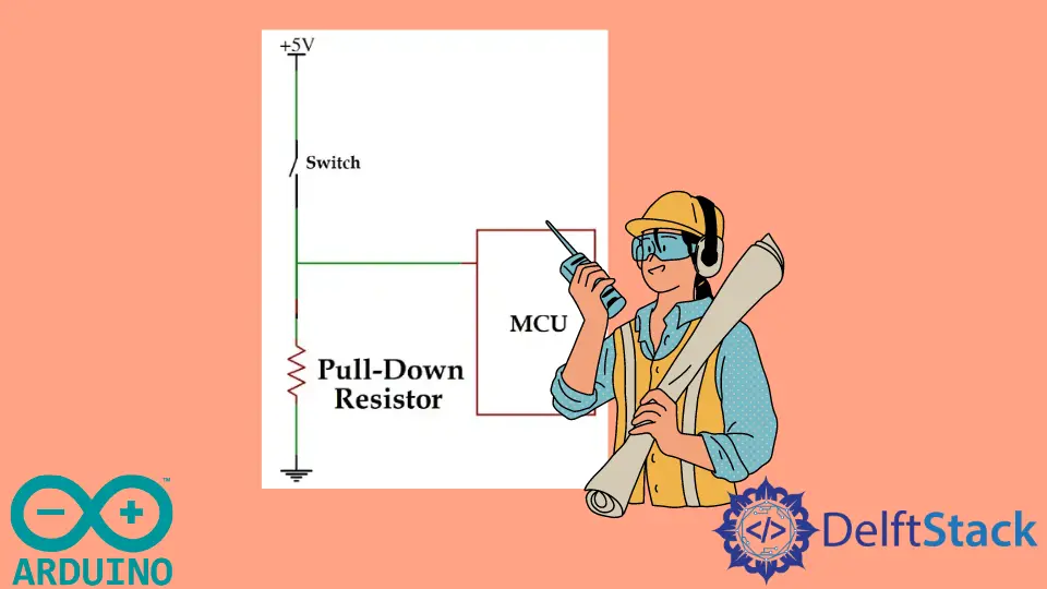
A pull-down resistor connects the pin with the ground if the switch is open, so the pin will only read LOW. To connect a pull-down resistor with a switch, check the below figure:
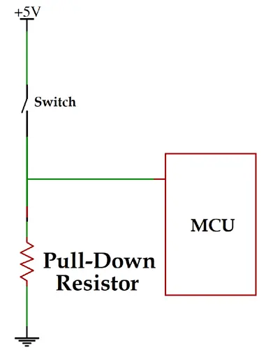
The value of the resistor should be between 1k to 100k. If you use a very low-value resistor, a high current will flow to the power ground when the switch is closed, and it can damage the Arduino.
The 5V and GND pins are present in Arduino so that you can use them with your switch and pull-down resistor.
If the switch is closed, the pin will be directly connected to the 5V, and the pin will be in a HIGH state. If the switch is open, the pin will be connected to the ground, and the pin will be in a LOW state.
Implementing Pull-Down Resistors in Arduino
Start by connecting one end of the pull-down resistor to the digital input pin on the Arduino (e.g., pin 2). Connect the other end to the ground (GND) pin on the Arduino.
Additionally, connect one terminal of the switch to the same digital pin and the other terminal to the 5V output on the Arduino.
If you are setting up conditional logic for Arduino, you may benefit from understanding more about the Arduino if Statement.
Open the Arduino IDE and create a new sketch. Start by defining the pin assignments using const int for better code readability.
Declare the digital pin for the switch input and define it as an input using the pinMode() function.
const int switchPin = 2; // Define the switch pin
void setup() {
  pinMode(switchPin, INPUT);  // Set switch pin as INPUT
}
In the loop() function, use the digitalRead() function to read the state of the switch. This function returns HIGH if the switch is closed and LOW if it is open.
Consider reading How to Wait for Input in Arduino to manage user inputs effectively in your Arduino projects.
void loop() {
  int switchState = digitalRead(switchPin);

  // Your code based on the switch state
}
Since we have connected a pull-down resistor, the input pin should read LOW when the switch is open and HIGH when the switch is closed. Adjust your code accordingly to perform specific actions based on the switch state.
void loop() {
  int switchState = digitalRead(switchPin);

  if (switchState == HIGH) {
    // Switch is closed; perform actions accordingly
  } else {
    // Switch is open, perform actions accordingly
  }
}
External Pull-Down Resistor with Analog Pin in Arduino
While Arduino boards do not have an explicit external pull-down resistor like they have internal pull-up resistors, you can certainly implement an external pull-down resistor in your circuit. The concept of a pull-down resistor involves connecting a resistor between the input pin and ground (GND) to ensure a stable low signal when the switch is open.
Example Code:
const int switchPin = A0;  // Analog pin connected to the switch

void setup() {
  pinMode(switchPin, INPUT);  // No pull-up or pull-down, relying on external
                              // pull-down resistor
  Serial.begin(9600);
}

void loop() {
  if (analogRead(switchPin) < 100) {
    Serial.println("Switch pressed!");
    delay(500);  // Debouncing delay
  }
}
In this code, the pinMode(switchPin, INPUT) configures the analog pin as an input without enabling any internal pull-up or pull-down resistor. Relying on an external pull-down resistor connected between the analog pin and GND.
For details on managing serial inputs, you may find How to Clear Serial Buffer in Arduino beneficial.
The if (analogRead(switchPin) < 100) reads the analog value of the switch pin. If the switch is pressed, the analog reading will be low (near 0) due to the external pull-down resistor.
Then, it outputs a message to the serial monitor when the switch is pressed. The delay(500) introduces a debouncing delay to prevent multiple rapid readings when the switch is pressed.
Internal Pull-Up Resistor With a Switch in Arduino
An internal pull-up resistor in Arduino is a feature that allows you to enable a resistor internally within the microcontroller to pull a digital input pin to a HIGH state when the pin is not actively being driven LOW by an external device. This is particularly useful when working with buttons, switches, or other digital input devices.
Example Code:
const int switchPin = 2;  // Digital pin connected to the switch

void setup() {
  pinMode(switchPin, INPUT_PULLUP);  // Internal pull-up resistor enabled
  Serial.begin(9600);
}

void loop() {
  if (digitalRead(switchPin) == LOW) {
    Serial.println("Switch pressed!");
    delay(500);  // Debouncing delay
  }
}
In this code, the pinMode(switchPin, INPUT_PULLUP) configures the switch pin as an input with the internal pull-up resistor enabled. The internal pull-up resistor connects the pin to VCC when the switch is open, ensuring a default HIGH state.
The if (digitalRead(switchPin) == LOW) checks if the switch is pressed by reading the digital state of the switch pin. If the switch is pressed, the input will be LOW because the pull-up resistor is overridden.
Then, it outputs a message to the serial monitor when the switch is pressed. The delay(500) introduces a debouncing delay to prevent multiple rapid readings when the switch is pressed.
Conclusion
This article provides a detailed exploration of pull-down resistors and their crucial role in ensuring stable digital input when working with switches in Arduino projects. Starting with the theoretical foundation, the article explains the purpose of pull-down resistors, addresses the floating state issue, and clarifies how they function in a circuit.
The practical implementation of pull-down resistors with switches is comprehensively covered, offering step-by-step instructions and example code snippets for both internal and external pull-down resistor setups. Key considerations such as resistor values and circuit connections are discussed, accompanied by visual representations.
In addition to exploring pull-down resistors, learning how to Make a Counter in Arduino can enhance the functionality of your projects by providing real-time data counting mechanisms.
The article extends its coverage to alternative scenarios, including the use of external pull-down resistors with analog pins and internal pull-up resistors for digital input devices. Example codes are provided to enhance understanding.
In conclusion, the article emphasizes the importance of mastering pull-down resistors for reliable Arduino projects. It assures readers that a solid grasp of these fundamentals enhances project reliability and contributes to the overall skill set of Arduino developers.