How to Create a Square Wave Generator in Arduino
-
Use the
digitalWriteFunction to Create a Square Wave Generator in Arduino - Use Timer Interrupts to Create a Square Wave Generator in Arduino
- Use Pulse Width Modulation (PWM) to Create a Square Wave Generator in Arduino
- Direct Port Manipulation to Create Square Wave Generator in Arduino
- Conclusion

A Square Wave Generator is a fundamental electronic circuit that produces a waveform characterized by a square shape. In Arduino, generating square waves is a common requirement for various applications, including signal generation, frequency modulation, and testing.
In this article, we will explore different methods to create a Square Wave Generator using Arduino. Each method will be accompanied by an example code, thoroughly explained to provide a comprehensive understanding.
Use the digitalWrite Function to Create a Square Wave Generator in Arduino
A square wave consists of a maximum and a minimum value, and the transition between these values is instantaneous. The maximum and minimum values duration is the same in a square wave.
For example, a square wave can have a minimum value of 0 and a maximum value of 1 with a time duration of 1 second for each value. A square wave is shown in the below diagram.
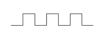
A square wave also has a specific frequency that specifies the number of cycles a square wave will have in a one-second duration. A frequency value of 60 Hz means that the wave is completing 60 cycles in one second.
We can generate a square wave in Arduino using the digitalWrite() function.
Syntax:
digitalWrite(pin_num, value)
The above syntax sets the given PIN specified by the pin_num variable to HIGH or LOW specified by the value variable. In Arduino, the LOW pin status means 0 volts, and the HIGH pin status means 5 volts or 3.3 volts, depending on the Arduino board.
To generate a square wave, we have to set the value of a digital pin to LOW, and after some delay, we have to set the value of the digital pin to HIGH. Before setting the value of a digital pin, we have to set the mode for the pin, like INPUT or OUTPUT, because there is a pull-up resistor present with each digital pin, which will lower the voltage value if we don’t set the mode of a digital pin.
We can use the pinMode() function to set the mode for a pin. We have to pass the PIN as the first argument and pin mode like OUTPUT or INPUT as the second argument inside the pinMode() function to set the mode of a digital pin.
We also have to add a delay after setting the value of a digital pin, and we can use the delay() or delayMicroseconds() function to add a delay in the Arduino code. The delay() function will set the given delay in milliseconds, and the delayMicroseconds() function will set the given delay in microseconds. To implement precision timing with delays in microseconds, you might want to explore how to add delay in microseconds in Arduino.
Let’s generate a square wave with a 10 Hz frequency in Arduino.
int f_hz = 10;

double delay_time = 1000 / (f_hz * 2);

void setup() { pinMode(11, OUTPUT); }
void loop() {
  digitalWrite(11, LOW);
  delay(delay_time);

  digitalWrite(11, HIGH);
  delay(delay_time);
}
We calculated the delay time in the above code using the 1/f formula, where f is the square wave frequency. We multiplied the time period by 1000 because we used the delay() function, which sets the delay in milliseconds, and to convert the time from seconds to milliseconds, we multiplied the time period by 1000.
To check the output waveform and frequency, we have to use an oscilloscope, or we can use an LED with pin 11, which will blink if the frequency is low. To use the oscilloscope, we have to connect the positive terminal of the oscilloscope with pin 11 and the negative terminal to the ground of the Arduino.
We have also divided the time period with 2 because we have two pulses in a single cycle, and we will set the delay value equal to half of the total time period after setting the digital pin to LOW and the other half time period will be used to set the delay after the setting the digital pin to HIGH. We can see in the above code we have used the delay() function twice.
The data type of the input value of the delay() function is unsigned long, and if we want to add a delay that is less than 1 millisecond, we have to use the delayMicroseconds() function which can add delay in microseconds. We can generate high-frequency square waves using the delayMicroseconds() function.
Note that the delay() and delayMicroseconds() functions do not support floating-point numbers, so we have to set a frequency value that should not generate the time period as a floating-point number. Adding delay in the Arduino code will also halt the other operations of Arduino because Arduino will not move to the next line of code until the delay time is finished, but PWM and interrupts will continue to work.
If we want to generate the square wave and perform some other task simultaneously, we can use the millis() function, which will return the time in milliseconds since the program started running. We can use the Arduino millis() function and the if statement to check the elapsed time, and if the elapsed time is equal to or greater than the time period, we will change the status of the digital pin.
Check this site for more details about the millis() function, and this site for delayMicroseconds() function. Click this link for details about the delay() function, and this link for the digitalWrite() function.
We can also use the analogWrite() function to create a square wave, but we cannot define its frequency. The frequency is already defined, mostly 499 Hz, or in the case of some pins, the frequency is 1000 Hz.
We must pass the PIN as the first argument and the wave’s duty cycle, which should be 127, as the second argument inside the analogWrite() function to generate a square wave. We have to pass 127 as the second argument because it will set the duty cycle to half, which is necessary to generate a square wave.
Click this link for frequency details of PWM pins and more information about the analogWrite() function.
Use Timer Interrupts to Create a Square Wave Generator in Arduino
In Arduino, timers are hardware modules that can be configured to generate interrupts at specific intervals. Timer interrupts enable the execution of code with precise timing, making them suitable for tasks like waveform generation.
For square wave generation, we will leverage a timer interrupt to toggle the state of a digital pin, creating a square wave with a specified frequency. You might find it useful to learn how to make a counter in Arduino using similar timer functionalities.
Example Code:
const int squareWavePin = 9;         // Digital pin for the square wave
volatile int squareWaveState = LOW;  // Initial state of the square wave

void setup() {
  pinMode(squareWavePin, OUTPUT);  // Set the digital pin as an output
  configureTimerInterrupt();       // Configure the timer interrupt
}

void loop() {
  // The square wave is generated using interrupts, so the loop is empty
}

void configureTimerInterrupt() {
  cli();  // Disable interrupts during configuration

  // Configure Timer1 for CTC (Clear Timer on Compare Match) mode
  TCCR1A = 0;  // Set TCCR1A register to 0
  TCCR1B = 0;  // Set TCCR1B register to 0

  // Set the Compare Value (OCR1A) for desired frequency
  OCR1A = 31249;  // For a frequency of 1 Hz (adjust as needed)

  // Configure Timer1 for interrupt on Compare Match
  TCCR1B |= (1 << WGM12);               // Enable CTC mode
  TCCR1B |= (1 << CS12) | (1 << CS10);  // Set prescaler to 1024

  // Enable Timer1 interrupt
  TIMSK1 |= (1 << OCIE1A);  // Enable interrupt on Compare Match

  sei();  // Enable interrupts after configuration
}

ISR(TIMER1_COMPA_vect) {
  squareWaveState = !squareWaveState;            // Toggle the square wave state
  digitalWrite(squareWavePin, squareWaveState);  // Set the pin to the new state
}
In this code, we first define the digital pin for the square wave and a volatile variable to store the current state. In the setup() function, set the specified digital pin as an output and call the function to configure the timer interrupt.
Since the square wave is generated using interrupts, the loop() function is left empty. The configureTimerInterrupt() function is responsible for configuring Timer1 for the CTC mode, setting the Compare Value for the desired frequency, and enabling the interrupt.
The ISR is executed when Timer1 reaches the Compare Value. It toggles the square wave state and sets the specified digital pin accordingly.
Use Pulse Width Modulation (PWM) to Create a Square Wave Generator in Arduino
PWM is a method that involves modulating the width of the pulse in a square wave. The duty cycle, which is the ratio of the pulse duration to the total period, determines the average power delivered to the load.
For example, a 50% duty cycle means the pulse is ON for half the time and OFF for the other half.
Arduino boards are equipped with PWM-capable pins, allowing for easy generation of PWM signals. The most commonly used Arduino boards, such as the Arduino Uno, have six PWM pins labeled from 3 to 11.
These pins are capable of producing PWM signals using the analogWrite() function.
To create a square wave generator, we’ll leverage the PWM capabilities of Arduino to generate a digital signal with varying duty cycles. Follow the steps below to create a simple square wave generator using an Arduino Uno:
Step 1: Choose a PWM Pin
Select a PWM-capable pin on the Arduino board. For this example, we’ll use pin 9.
Step 2: Set Up the Arduino
Connect the chosen PWM pin to the load, which can be an LED or any other device. Additionally, connect the Arduino board to your computer using a USB cable.
Step 3: Write the Arduino Code
Write a simple Arduino sketch to generate a square wave with a variable duty cycle. Below is an example code:
const int pwmPin = 9;

void setup() { pinMode(pwmPin, OUTPUT); }

void loop() {
  for (int dutyCycle = 0; dutyCycle <= 255; dutyCycle += 5) {
    analogWrite(pwmPin, dutyCycle);
    delay(100);  // Adjust the delay for desired frequency
  }
}
This code gradually increases the duty cycle from 0 to 255, creating a smooth transition in LED brightness or any other connected load.
Step 4: Upload and Run
Upload the code to your Arduino board using the Arduino IDE. You should observe the connected load (LED) varying in brightness as the duty cycle changes.
Direct Port Manipulation to Create Square Wave Generator in Arduino
In Arduino, direct port manipulation involves manipulating the port registers directly to set or clear the state of multiple pins simultaneously. This technique is powerful and efficient, making it suitable for tasks where speed and accuracy are crucial.
To create a square wave using direct port manipulation, we’ll toggle the state of a specific pin by XORing its state with a mask.
Example Code:
const int squareWavePin = 9;  // Digital pin for the square wave

void setup() {
  pinMode(squareWavePin, OUTPUT);  // Set the digital pin as an output
  configureSquareWaveGenerator();  // Configure square wave generation
}

void loop() {
  // The square wave is generated using direct port manipulation, so the loop is
  // empty
}

void configureSquareWaveGenerator() {
  // Set the initial state of the square wave pin
  PORTB &= ~(1 << PB1);  // Clear bit 1 (square wave pin) to set it to LOW

  // Configure Timer1 for CTC (Clear Timer on Compare Match) mode
  TCCR1A = 0;  // Set TCCR1A register to 0
  TCCR1B = 0;  // Set TCCR1B register to 0

  // Set the Compare Value (OCR1A) for desired frequency
  OCR1A = 31249;  // For a frequency of 1 Hz (adjust as needed)

  // Configure Timer1 for interrupt on Compare Match
  TCCR1B |= (1 << WGM12);               // Enable CTC mode
  TCCR1B |= (1 << CS12) | (1 << CS10);  // Set prescaler to 1024

  // Enable Timer1 interrupt
  TIMSK1 |= (1 << OCIE1A);  // Enable interrupt on Compare Match
}

ISR(TIMER1_COMPA_vect) {
  // Toggle the state of the square wave pin using direct port manipulation
  PORTB ^= (1 << PB1);  // XOR operation to toggle bit 1 (square wave pin)
}
In this code, we first define the digital pin for the square wave. In the setup() function, set the specified digital pin as an output and call the function to configure the square wave generator.
Since the square wave is generated using direct port manipulation, the loop() function is left empty. The configureSquareWaveGenerator() function is responsible for setting the initial state of the square wave pin, configuring Timer1 for the CTC mode, and enabling the Timer1 interrupt.
The ISR is executed when Timer1 reaches the Compare Value. It toggles the state of the square wave pin using direct port manipulation.
Conclusion
Creating a Square Wave Generator in Arduino involves various methods, each suitable for different scenarios and user requirements. Whether using basic digitalWrite, utilizing timer interrupts, leveraging PWM, or employing direct port manipulation, Arduino provides flexibility to meet diverse needs.
Selecting the appropriate method depends on factors such as precision, frequency, and the complexity of the desired waveform. By exploring these methods, developers can gain a deeper understanding of Arduino’s capabilities in waveform generation and enhance their ability to design and implement electronic projects.